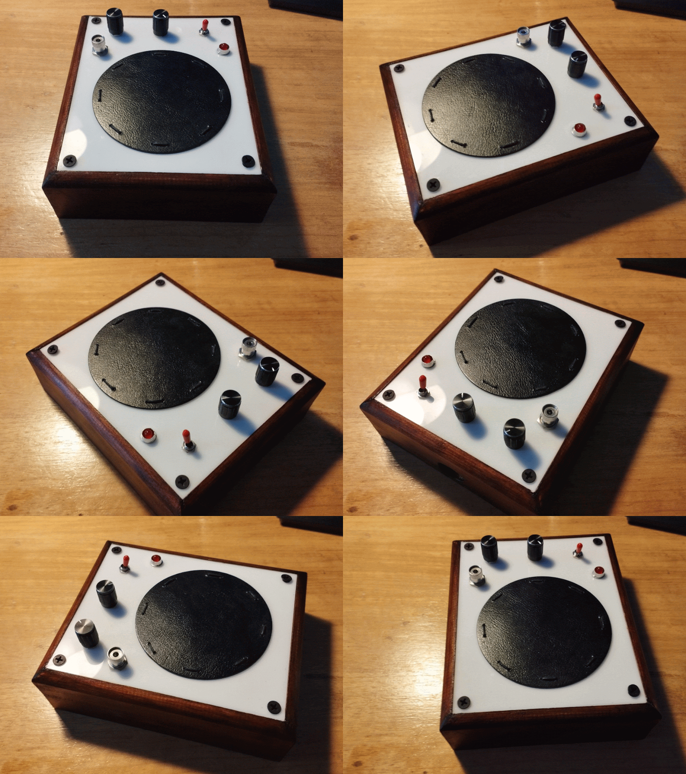
Here’s how your panel should look after adding the components. Note, this is the back of the front panel. Does that make sense? Here’s a real life image just to confirm:
The Piezo cables should be poking through a small drill-hole in the case, and you should also take into account the LED legs > The shorter should be on the left, the longer on the right.
__________________________________________________________________
2.
Add a wire between the volume & pitch knobs, leave some space on the pitch knob pin, as we’ll be adding another wire to it next (you can even hold off soldering this connection until you’ve added the next wire if you find it easier).
__________________________________________________________________
3.
Before we join the next wire, you need to be sure you’re soldering to the correct lug of the audio jack. We want to join to the ground lug, which is shown in the below picture connected to the black wire.
Notice how this is joined to the base/center of the audio jack, whereas the lug with the red wire appears not to be joined to anything (it’s actually connected to the tallest part of the audio jack, the part where once the heaphone jack is inserted, the tip touches). You can confirm this by using a multimeter.
So now you know which part of the audio jack is ground, connect the wire to it. Again, try and leave some room, as in the next step we’ll be adding a second wire to this connection.
_____________________________________________________________________
4.
Now we add another wire from the audio jack. Eventually this wire will join to the circuit board, so you’ll want to make it long enough so we can comfortably work on both the board and the panel. I’d say 10cm would be perfect.
_____________________________________________________________________
5.
Run a cable from the volume pot to the positive side of the audio jack;
____________________________________________________________________
6.
Connect a cable from the pitch pot to the bottom for the switch lugs. We’ll be adding another wire to the bottom of the switch next, so be prepared for this.
_______________________________________________________________________
7.
Add a 10cm bit of wire from the bottom of the switch. This will get connected to the circuit board eventually.
___________________________________________________________________
8.
Add a 10cm bit of wire to the centre of the switch.
_____________________________________________________________________
9.
Add a 10cm bit of wire to the top of the switch.
_____________________________________________________________________
10.
Add a 10cm piece of wire from the Volume pot;
_____________________________________________________________________
11.
Add a 10cm piece of wire from the Pitch pot;
______________________________________________________________________
12.
Now we add a 10cm piece of wire from the shorter leg of the LED. We never want the metal legs of the LED to touch each other, so you may wish to trim this short leg even shorter to stop this from happening. You can even cover the joins with heat shrink tubing if you’re particularly fussy. Just make sure you remember which leg was the shorter one.
Tip: joining the wire to a leg can be made easier if you bend each connection into a ‘V’ shaped hook, hook both parts together, then bend flat to join with pliers, then solder.
____________________________________________________________________
13.
Now finally we add one last piece of 10cm wire…
That’s the panel finished, now we just need to join it to the circuit board.
Join The Circuit Board to The Front Panel
************************************************************************
Overview: Now it’s time to join the circuit board to the front panel. Hopefully you’ve used the advised 10cm pieces of wire, as that will make turning the circuit board over easier. Not to worry if you haven’t, it’ll just be slightly more fiddly. You might notice the two Piezo pieces of wire aren’t 10cm… so we’ll solder those last.
1.
First we’ll join the shorter LED wire to the board:
Join it to the 1k resistor;

_________________________________________________________
Now for the longer LED leg;
Connect it to the 5v Arduino pin
________________________________________________________
3.
Now take the middle pitch wire…
____________________________________________________
4.
Middle Vol wire;
Join to the resistor/capacitor connection
______________________________________________________
5.
Take the audio ground wire….
…then join this wire to the other side of the capacitor connection…
___________________________________________________
6.
Take the top switch wire;
…Join that to the Arduino GND
___________________________________________________
7.
Now the middle switch wire…
______________________________________________________
8.
Take the bottom switch wire;
…connect with the Arduino 5v
_____________________________________________________
9.
Now we’re nearing the end. Take the black Piezo wire…
…and join it to the bottom of the board to the diode
_________________________________________________________
10.
Now finally, take the red Piezo wire…
…and join it to the bottom of the board, the opposite side of the last wire;
We now should have a working drum-pad-thing. Plug it in and give it a try.


